Taking a negative analog input onto your micro-controller or prototyping device becomes necessary at times, specially when dealing with applications like sound recognition, reading EMG signals, ECG signals, working with OpAmps etc. While your micro-controller can (probably) sense between 0V-5V or 0V-12V, this little hack will double the capability to accommodate negative inputs as well, expanding your range to -5V – +5V or -12V – +12V. This hack is valid for Arduino-based devices and most micro-controllers in general. It will also be useful for evive users who wish to sense negative voltages from it’s Arduino pin-outs.
Micro-controllers like Arduino can take only positive voltage input at its pins. The method elucidated below takes both negative and positive values and sends them to Arduino along with the sign information. The idea is to take both the original input and an inverted one and select one of them using a multiplexer. So we can get the positive input as it is and the negative input in an inverted form. The sign can be determined using the output of a comparator which is subjected to the same input as the differential amplifiers.
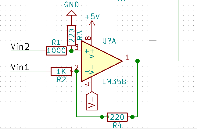
I have used two differential amplifiers. One amplifier gives output V1-V2 and the other V2-V1. (The circuit for both of them is the same we can give inverted input to one of the amplifiers).
The differential amplifier gives an isolated input so that one does not have to keep ground of the input common with the micro-controller. I would want to read input from one of the two amplifiers using my micro-controller. For this I use the CD4053 mux and use output of the comparator to select outputs from the mux. The comparator is given the same input as the two differential amplifiers.

You can read more about this circuit on our step-by-step guide here. One problem that remains (in some cases) is that of power supply. If the op-amp is given +5 and zero volts, the op-amp saturates (on the lower voltage side) at around 500 mV. For the above design we do not need a -5V negative supply as the output of the op-amp (at least the one we need) is always positive. However, to get voltage values near 0V, an unregulated negative supply can be used.
One of the ways to create a negative voltage supply can be found in the article here. Note that the gain of the amplifier can be set according to one’s requirements by changing the values of the resistors. Also, if you need a regulated negative supply a 7905 regulator can be used after the 555 circuit.
evive uses ADE7912, an isolated analog to digital converter IC which simplifies the PCB design and gives better resolution. But it adds to the cost of a project so might not be very useful if such high resolution is not required. In such a scenario, the above circuit might be very useful.
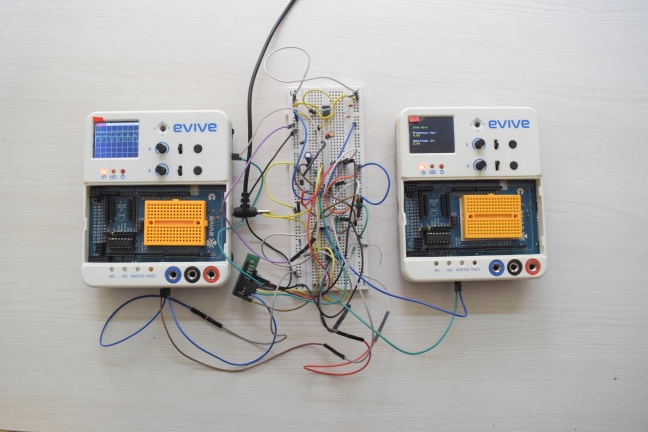

Pictures above show the circuit with a positive input and negative input respectively. Observe that the output sinusoid remains the same but the multimeter reading changes.
Submitted by: Harsh Chittora, a happy evive user!
Sick of this? evive solves this problem with it’s inbuilt systems, offering a range of -30V to +30V on its data acquisition channels, unlike any other platform on Earth. Find more about it’s features at http://learn.evive.cc/index.html?t=Features.